What is Toolmakers Microscope?
- The Toolmakers Microscope is a specialized instrument that differs from conventional light microscopes in its primary application. Unlike regular microscopes that are primarily used for observing and studying specimens, the toolmakers microscope is specifically designed as a precision measuring device. Its exceptional capability allows it to measure objects with an accuracy of up to 1/100th of a millimeter, making it a valuable tool in various industries that deal with miniature mechanical and electronic components.
- One of the key functions of the toolmakers microscope is the inspection and measurement of small parts. This capability is crucial in industries where even the slightest deviation can lead to significant consequences. For example, the toolmakers microscope is commonly employed for examining and measuring thread pitch and thread angles, among other critical measurements in manufacturing processes.
- The toolmakers microscope achieves its remarkable precision through its high magnification capabilities. By enlarging the object being observed, it allows the user to make accurate readings with ease. This level of magnification is essential for capturing intricate details of miniature parts that might not be visible to the naked eye.
- The simplicity and convenience of the toolmakers microscope make it an ideal choice for obtaining precise measurements. Its design enables both absolute and comparative measurements, providing flexibility in various measurement scenarios. This means it can be used to establish the exact dimensions of an object or to compare the dimensions of multiple objects against a standard, ensuring consistency and quality control in manufacturing processes.
- Understanding the basic principle of a microscope is crucial to grasp the functioning of the toolmakers microscope. At its core, a microscope works by utilizing lenses to bend and focus light, thereby magnifying the image of the object being observed. In the case of the toolmakers microscope, this principle is applied with exceptional precision to achieve accurate and reliable measurements of miniature components.
- In conclusion, the toolmakers microscope is a highly specialized instrument that serves as a precise measuring device, unlike regular light microscopes used for observation and study. Its ability to measure objects with incredible accuracy up to 1/100th of a millimeter makes it indispensable in industries dealing with small mechanical and electronic parts. By providing high magnification and simple yet efficient measurement capabilities, it ensures the precise inspection and quality control of crucial components in the manufacturing process.
Principle of Toolmakers Microscope
The working principle of the toolmakers microscope relies on the principles of optics, similar to a conventional light microscope. The microscope is equipped with a light source that directs light upward, focusing it onto the object being observed. When the light falls on the object, it casts a shadow, as light cannot pass through the object. However, this shadow closely resembles the object’s features, allowing for precise measurements to be taken.
The degree of magnification achieved by the toolmakers microscope primarily depends on the objective lens being used. The microscope is typically designed with the capability to provide a magnification range between 10x and 100x. Lower magnification levels allow for a broader view of the object, enabling the user to observe most parts of it at once. On the other hand, higher magnification levels provide a more detailed and clear image, especially when combined with appropriate adjustments to the illumination.
For the microscope to be adaptable to various applications, it may require a variety of attachments and accessories. These additional components ensure that the shadow image of the object accurately represents its true details, including its shape, intricate features, and, in some cases, even its color. To achieve this accuracy, the toolmakers microscope employs several special techniques and accessories, such as filters, lens coatings, and diaphragms. These elements are carefully selected and applied to influence the raw image produced by the microscope, resulting in more precise and reliable information.
By incorporating these optical principles and employing various attachments, the toolmakers microscope becomes a versatile instrument capable of accurately measuring and inspecting miniature mechanical and electronic parts. The ability to achieve different levels of magnification, along with the use of specialized accessories, ensures that the microscope can cater to a wide range of applications, providing essential data for quality control, manufacturing processes, and other precision-related tasks.
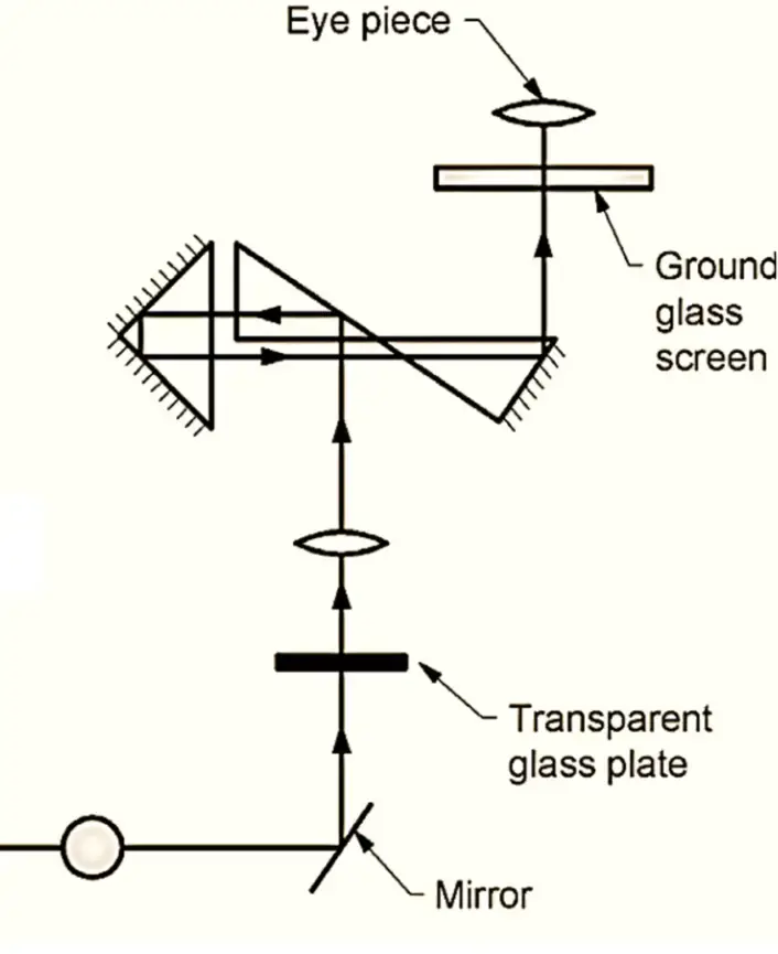
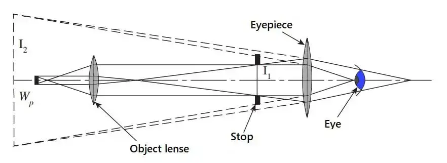
Parts of a Toolmakers Microscope
The toolmakers microscope is a precision measuring instrument that consists of several essential parts working together to provide accurate and reliable measurements. Each component plays a crucial role in the functionality and versatility of the microscope.
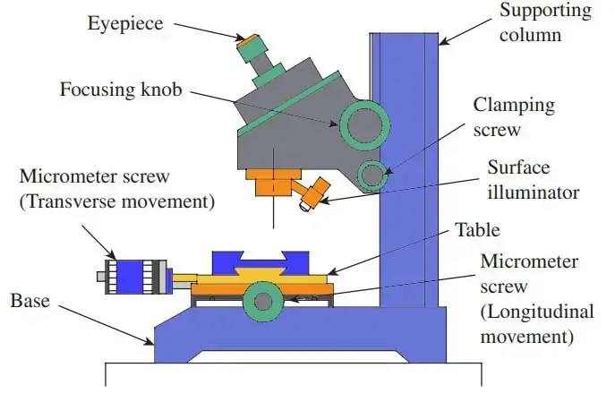
- Hollow Base: The toolmakers microscope is built upon a sturdy hollow base. This base serves as the foundation for the entire instrument and also accommodates the illumination unit located underneath. The base ensures stability during measurements, minimizing any vibrations that could affect the precision of the readings.
- Circular Stage Surface: Situated on the upper part of the base, the circular stage surface is a vital component of the toolmakers microscope. This stage is typically made of transparent glass, allowing light to pass through. It provides a flat and smooth platform where the object being measured is placed. The stage surface can be rotated a full 360 degrees, enabling easy positioning of the object for measurement from various angles.
- Objective Lens: The objective lens is one of the primary optical components of the toolmakers microscope. It is located above the stage and is responsible for magnifying the image of the object placed on the stage. This lens is carefully designed to offer high magnification capabilities, allowing the user to observe minute details of small components.
- Eyepiece: Positioned at the top of the microscope, the eyepiece is the lens through which the user looks to view the magnified image of the object. It further enhances the magnification achieved by the objective lens, resulting in a powerful combined magnification that aids in precise measurements.
- Micrometer Screws: The toolmakers microscope features two micrometer screws that play a crucial role in adjusting the position of the stage surface or table. One micrometer screw is responsible for longitudinal movement, which refers to movement along the length of the stage, while the other micrometer screw controls lateral movement, allowing side-to-side adjustments. These micrometer screws enable precise positioning of the object, essential for accurate measurements.
- Ground Glass Screen: The ground glass screen is an integral part of the toolmakers microscope, located at the top of the instrument. It acts as a focusing screen and assists in obtaining sharp and clear images of the object under observation. The ground glass screen ensures that the image viewed through the eyepiece is well-focused, making it easier for the user to take accurate readings.
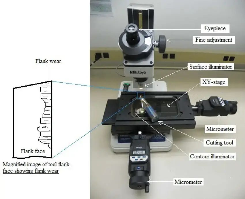
Construction and Working of Tool Maker’s Microscope
The construction and working of a Tool Maker’s Microscope involve several essential components and precise measurement techniques to ensure accurate readings. Here’s an overview of its construction and functioning:
Construction:
- Vertical Supporting Column: The microscope is built upon a sturdy vertical supporting column that bears the weight of all other parts. It provides stability to the entire instrument.
- XY Stage: The workpiece is placed on an XY stage, which allows translatory motion in two principal directions within the horizontal plane. This stage can be moved precisely using micrometers for linear measurement.
- Measuring Head: The optical system is housed within the measuring head. It can be moved up and down along the supporting column using a focusing knob to focus the image.
- Clamping Mechanism: The measuring head can be locked into position using a clamping screw to secure the desired focus and prevent unintended movements during measurements.
- Angle Dial: An angle dial is integrated into the eyepiece portion of the optical tube, enabling easy angle measurement during inspection.
- Surface Illuminator: A surface illuminator provides the necessary illumination of the object, ensuring a sharp and clear image for accurate measurements.
Working Principle:
- Reticle: The key element that transforms the microscope into a measuring instrument is the reticle. It provides a reference or datum for measurement when the image is viewed through the eyepiece.
- Linear Measurement: To perform linear measurements, a measuring point on the workpiece is aligned with one of the crosswires of the reticle, and the reading (R1) on the microscope is noted. The XY table is then moved using the micrometer head to align another measuring point with the same crosswire, and the reading (R2) is recorded. The difference between R1 and R2 represents the dimension between the two measuring points.
- Vernier Scales: In some tool maker’s microscopes, vernier scales are used for taking readings instead of a micrometer head. The vernier scale is precisely calibrated to enable accurate measurements.
- Dioptre Adjustment: A dioptre adjustment ring in the eyepiece mount ensures the crosswires of the reticle are brought into sharp focus, while the focusing knob moves the optical tube up and down to focus the measuring surface.
- Alignment: Proper positioning of the workpiece on the table is crucial for accuracy. The measuring direction of the workpiece should align with the traversing direction of the table. The eyepiece mount is adjusted so that the horizontal crosswire coincides with the table movement direction.
- Surface Illumination: The surface illuminator provides clear and sharp images of the workpiece. Different illumination modes can be selected based on the specific application requirements.
In conclusion, the Tool Maker’s Microscope is designed with precision in mind, featuring a robust construction and an array of measurement tools to achieve accurate readings of small mechanical and electronic parts. The integration of a reticle and the careful alignment of the workpiece ensure that the microscope functions effectively as a measuring instrument, making it an invaluable tool in various industries that demand high precision and accurate measurements.
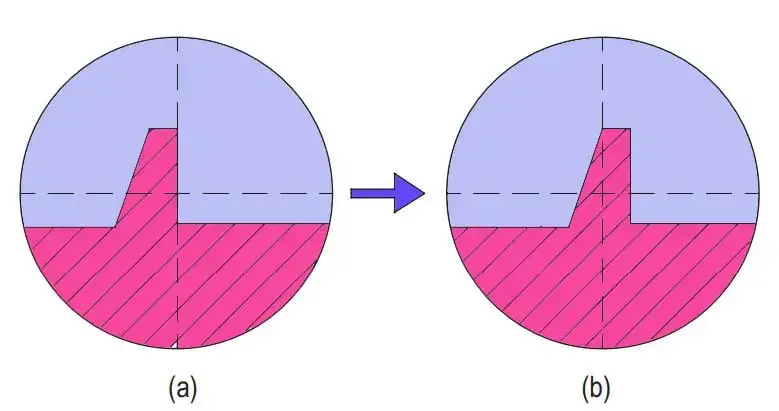
How to Use a Measuring Microscope
Using a measuring microscope is a straightforward process that requires careful positioning and observation. Here’s a step-by-step guide on how to use a measuring microscope effectively:
- Preparation:
- Ensure the measuring microscope is set up on a stable surface with proper lighting conditions.
- Clean the microscope’s lenses and stage to avoid any distortions or inaccuracies in the measurements.
- Select the appropriate lighting method (transmitted light or reflected light) based on the nature of the target.
- Place the Target on the Stage:
- Gently position the target, which could be a small mechanical or electronic part, on the stage of the measuring microscope.
- Make sure the target is securely placed and does not move during the measurement process.
- Align the Shadow with Reference Lines:
- Observe the target through the eyepiece and adjust the focus to obtain a clear image.
- Depending on the lighting method used, you will see a shadow of the target on the stage.
- Align the edge of the shadow with the reference lines on the reticle or scale of the microscope.
- Choose Suitable Lighting:
- Different lighting techniques can be employed depending on the characteristics of the target.
- For example, backlighting can be used to measure transparent or translucent objects, while coaxial illumination is suitable for highly reflective surfaces.
- Adjust the illumination to achieve the best possible contrast and clarity of the image.
- Take Measurements:
- Once the target is aligned with the reference lines, you can begin taking measurements.
- Many measuring microscopes are equipped with micrometers or vernier scales to record the position of the target accurately.
- By noting down the readings from the micrometer or vernier scale, you can determine the dimensions of the target with high precision.
- Output the Measured Values:
- Modern measuring microscopes often come with digital capabilities that allow the measured values to be output in various formats, such as CAD data.
- The data can be stored, processed, and used for further analysis or documentation.
- Verification and Calibration:
- Regularly calibrate the measuring microscope to ensure its accuracy and reliability.
- Perform verification checks using known standards or reference samples to confirm the instrument’s performance.
In conclusion, using a measuring microscope involves placing the target on the stage, aligning its shadow with reference lines, selecting appropriate lighting, and taking precise measurements using micrometers or vernier scales. The modern capabilities of measuring microscopes allow for easy output of the measured values as CAD data, providing valuable information for quality control, manufacturing processes, and other precision-related applications. Regular calibration and verification ensure the instrument’s accuracy, making it an indispensable tool for industries that demand precise measurements of small components.
Simple Experiments
Pitch measurement of a hacksaw blade
The procedure for measuring the pitch of a hacksaw blade using a measuring microscope involves precise steps to ensure accurate results. Here’s a step-by-step guide:
- Switch on the Microscope Light: Start by switching on the light source of the measuring microscope to illuminate the workspace. Proper illumination is essential for obtaining a clear and sharp image of the hacksaw blade.
- Select Lens for Precision Operation: Choose the appropriate lens on the measuring microscope that provides the desired level of magnification for precise pitch measurement. The selection of the lens depends on the specific features and dimensions of the hacksaw blade.
- Place the Blade and Glass Table (Stage): Position the hacksaw blade on the glass table or stage of the measuring microscope. Make sure the blade is securely placed and does not move during the measurement process.
- Rotate the Wheel for Clear Image: Use the wheel or knob on the right side of the microscope to adjust the focus and obtain a clear image of the hacksaw blade. Proper focusing ensures that the edges of the blade are sharp and well-defined.
- Align Cross Line with Blade Edge: Ensure that the cross line or reticle of the measuring microscope coincides precisely with one of the edges of the hacksaw blade. This alignment is crucial for accurate pitch measurement.
- Take Initial Reading: Once the cross line is aligned with one edge of the blade, note down the reading displayed on the ground glass screen or reticle. This reading represents the initial position of the microscope’s stage.
- Rotate the Table for Second Reading: Carefully rotate the table of the measuring microscope until the next edge of the hacksaw blade comes into focus and aligns with the cross line or reticle.
- Take Second Reading: Note down the reading displayed on the ground glass screen or reticle once the second edge of the blade is aligned with the cross line. This reading represents the new position of the microscope’s stage.
- Calculate the Pitch: To determine the pitch of the hacksaw blade, subtract the initial reading (Step 6) from the second reading (Step 8). The difference between the two readings represents the distance between two consecutive teeth or pitch of the hacksaw blade.
- Repeat Measurements: For increased accuracy, repeat the measurement procedure multiple times and calculate the average pitch value.
By following this procedure, the pitch of a hacksaw blade can be accurately measured using a measuring microscope. The microscope’s precision and ability to provide high magnification contribute to obtaining reliable and consistent pitch measurements, ensuring the blade’s quality and performance in various cutting applications.
Obtaining the angle of the hacksaw teeth
The procedure for obtaining the angle of the hacksaw teeth using a measuring microscope involves precise steps to ensure accurate measurements. Here’s a step-by-step guide:
- Place the Blade on the Glass Table: Start by positioning the hacksaw blade on the glass table or stage of the measuring microscope. Ensure that the blade is securely placed, and the teeth of the hacksaw are visible for measurement.
- Rotate the Screen for Highlighted Line: Use the adjustments on the measuring microscope to rotate the screen until a specific line or reference point on the angle of screen rotation is highlighted. This line will serve as a reference for angular measurements.
- Take Initial Angular Reading: Once the highlighted line is in position, note down the initial angular reading displayed on the measuring microscope. This reading represents the starting point of the measurement.
- Rotate the Screen Again for Second Reading: Carefully rotate the screen or stage of the measuring microscope until the highlighted line coincides with another flank or edge of the hacksaw tooth.
- Take Second Angular Reading: Note down the angular reading displayed on the measuring microscope when the highlighted line aligns with the second flank of the hacksaw tooth. This reading represents the new position of the measurement.
- Calculate the Angle: To determine the angle of the hacksaw teeth, calculate the difference between the initial angular reading (Step 3) and the second angular reading (Step 5). The difference between the two readings represents the angle of the hacksaw tooth.
- Repeat Measurements: For increased accuracy, repeat the procedure multiple times on different teeth of the hacksaw blade and calculate the average angle value.
Handling Precautions
Handling precautions are essential to ensure the accuracy and longevity of measuring microscopes. These precautions help maintain a clean and stable environment for the instrument, allowing it to perform precise measurements effectively. Here are some crucial handling precautions for measuring microscopes:
- Clean Environment: Measuring microscopes, like general-purpose microscopes, should be used in a clean environment free of dust and debris. Dust particles can interfere with the accuracy of measurements and affect the quality of the images observed. Regularly clean the lenses, stage, and other parts of the microscope to keep it free from dust.
- Stable Installation: The stand or surface on which the measuring microscope is installed should be level and stable. Avoid placing the microscope on surfaces that may vibrate or have excessive movements, as this can lead to inaccurate measurements. A stable installation ensures consistent and reliable results.
- Dust Cover: After use, always remember to cover the measuring microscope to protect it from dust and contaminants. Dust adhering to the lenses or other optical components can degrade the image quality and impact the accuracy of measurements. Using a dust cover helps maintain the cleanliness of the microscope and preserves its performance.
- Proper Storage: When not in use for an extended period, store the measuring microscope in a safe and clean environment. Avoid exposing it to extreme temperatures or humidity, as these conditions can damage the delicate optical and mechanical components of the instrument.
- Regular Calibration: Measuring microscopes require periodic calibration to ensure accurate measurements. The calibration interval typically ranges from 1 to 3 years, depending on the manufacturer’s recommendations and the frequency of use. Regular calibration helps maintain the precision of the microscope and verifies its accuracy against known standards.
- Gentle Handling: Handle the measuring microscope with care and avoid rough or forceful handling. Delicate components, such as the lenses and stage, can be damaged by excessive force. Always use the appropriate controls and knobs to adjust focus and position the target gently.
- Avoid Excessive Light Exposure: Prolonged exposure to intense light sources can lead to damage to the microscope’s lenses and optical components. When not in use, keep the microscope away from direct sunlight or strong artificial light to preserve its optical integrity.
- Follow Manufacturer’s Guidelines: Adhere to the manufacturer’s guidelines and instructions for operating and maintaining the measuring microscope. Different models may have specific requirements and recommendations, and following them ensures optimal performance and longevity of the instrument.
By following these handling precautions, users can ensure that the measuring microscope functions accurately and reliably throughout its operational life. Proper care and maintenance not only enhance the microscope’s performance but also contribute to the consistent quality of measurements, making it a valuable tool in various precision-related applications.
Applications of Tool Maker’s Microscope
The toolmakers microscope is a versatile instrument with a wide range of uses in various industries that deal with small and precise components. Its high magnification capabilities and accurate measurement features make it an indispensable tool in several applications:
- Shop Floor Inspection: One of the primary uses of the toolmakers microscope is in the shop floor inspection of small machine parts, screw threads, and gears. It allows technicians and engineers to closely examine these components for any defects, ensuring that they meet the required specifications and tolerances.
- Precision Measurement in Tool Rooms: Toolmakers microscopes are commonly used in tool rooms for precise measurement of test tools. These microscopes provide accurate readings and help ensure that the tools are correctly calibrated and meet the required standards.
- Measurement of Small Holes: Toolmakers microscopes are utilized for determining the dimensions of small holes that cannot be easily measured with conventional tools like micrometers and calipers. The high magnification and precision of the microscope enable accurate measurement of these tiny features.
- Template Matching Inspection: The microscope facilitates template matching inspection, particularly for small screw threads and involute gear teeth. Optional template reticles can be used to compare the profiles and ensure the components are manufactured with the correct specifications.
- Inspection of Tapers: Toolmakers microscopes are capable of inspecting tapers on small components with remarkable accuracy, up to 1/100th of a millimeter. This is crucial for industries where precise taper angles are essential for proper functioning.
- Determining Relative Positions: The toolmakers microscope is utilized for determining the relative positions of different points on an object. By measuring the travel required to bring one point to the position formerly occupied by another, technicians can establish accurate spatial relationships.
- Measuring Angles: The microscope allows for precise measurement of angles using the protractor eyepiece. This feature is valuable in industries where accurate angle measurements are critical for proper assembly and functionality.
- Comparison Measurement: The toolmakers microscope is employed to compare thread forms, measuring pitch, and diameter. By utilizing master profiles engravings in the eyepiece, technicians can ensure that components meet the required specifications.
- Comparing with a Scale: The microscope’s projection screen enables images of the object to be compared with a scale, aiding in measurements and ensuring components are manufactured with the correct dimensions.
In conclusion, the toolmakers microscope finds extensive use in industries that require precise measurements of small components and intricate details. From inspecting screw threads and gears to measuring angles and determining relative positions, this instrument plays a vital role in maintaining quality control and precision in manufacturing processes and tool rooms. Its versatility and accuracy make it an essential tool for any industry that deals with miniature mechanical and electronic parts.
Advantages of Tool Maker’s Microscope
The toolmaker’s microscope is a valuable and versatile device that plays a crucial role in various industries, allowing manufacturers and technicians to observe and measure small parts with precision. It offers numerous advantages that make it well-suited for such tasks. Some of the key advantages of the toolmaker’s microscope are as follows:
- Z-Axis Height Information: Unlike optical comparators, the toolmaker’s microscope is preferred when z-axis height information is required. This capability allows for accurate measurements of the height and depth of small components, providing valuable data for quality control and manufacturing processes.
- Equipped with Linear Scales: The stage of the toolmaker’s microscope can be equipped with linear scales, enabling direct and precise measurements of distances and dimensions. This feature enhances the accuracy of measurements, making it ideal for tasks that demand high precision.
- Compatibility with Cameras and CCTV: The toolmaker’s microscope can easily adapt to both cameras and CCTV systems for photo documentation requirements. This allows users to capture images and videos of the observed components for documentation, analysis, and quality assurance purposes.
- Variety of Optical Techniques: The toolmaker’s microscope offers a range of optical techniques, allowing users to employ specific methods that suit their measurement needs. It can use optics with higher magnification resolution, enabling better measuring accuracy for intricate and small components.
- Measurement of Hardness Test Indentations: It is well-suited for measurements of hardness test indentations. The microscope’s precise measurement capabilities make it an essential tool for assessing the hardness of materials, a critical aspect in materials testing and engineering.
- Adaptability for Various Applications: The toolmaker’s microscope can be adapted for various applications, making it a versatile tool across different industries. It is used in fields such as manufacturing, toolmaking, electronics, quality control, and research, among others.
- Surface Finish Verification and Defect Measurement: For those involved in repairing tools and electronic parts, the toolmaker’s microscope is an effective tool for verifying surface finish and measuring defects on surfaces. This feature aids in identifying imperfections and ensuring the quality of the finished products.
- Precise Measurements: One of the primary advantages of the toolmaker’s microscope is its ability to provide precise measurements. Its high magnification capabilities and accurate measurement tools allow for detailed inspections and precise readings of small components.
In conclusion, the toolmaker’s microscope offers numerous advantages, including z-axis height information, linear scale integration, compatibility with cameras and CCTV, and a variety of optical techniques. Its adaptability for different applications, ability to measure hardness test indentations, and capacity for precise measurements make it an indispensable tool in various industries and applications where accuracy and attention to detail are essential.
Disadvantages of Tool Maker’s Microscope
- Higher Cost: Toolmaker’s microscopes are typically more expensive compared to other types of microscopes due to their precision measurement and inspection capabilities. The inclusion of features like a built-in stage micrometer contributes to the increased cost.
- Complexity: These microscopes can be challenging to use, especially for inexperienced users, as they often have numerous controls and settings that require proper adjustment for accurate measurements.
- Fragility: Toolmaker’s microscopes are constructed with delicate and precise components that can be easily damaged if not handled with care. This makes their storage and transportation require careful attention.
- Bulky Design: Toolmaker’s microscopes are often larger and heavier than other microscope types, making them less convenient for certain applications, such as fieldwork or use in small workspaces.
- Calibration Demands: The accuracy of measurements obtained from toolmaker’s microscopes heavily relies on precise calibration. Improper calibration can result in inaccuracies in the measured values.
- Time-Consuming: Setting up and using a toolmaker’s microscope can be time-consuming, particularly when striving for accurate and precise measurements.
- Limited Versatility: Toolmaker’s microscopes may not be as versatile as other types of microscopes, like compound microscopes. They may not be well-suited for tasks involving transparent specimens or live cell observation.
FAQ
What is a toolmaker’s microscope, and what sets it apart from a conventional microscope?
A toolmaker’s microscope is a precision measuring instrument used to inspect and measure small mechanical and electronic parts. Unlike a conventional microscope, it is designed specifically for accurate measurements and can measure up to 1/100th of a millimeter.
What are the main applications of a toolmaker’s microscope?
Toolmaker’s microscopes are widely used in various industries for shop floor inspection of screw threads, gears, and small machine parts. They are also used for precision measurement of test tools in tool rooms and for determining dimensions of small holes and tapers.
How does a toolmaker’s microscope achieve magnification and accurate measurements?
Toolmaker’s microscopes use optical systems with high magnification capabilities, allowing users to view and measure small parts with precision. They also incorporate reticles or scales to provide reference points for accurate measurements.
Can a toolmaker’s microscope be used for non-destructive testing of materials?
No, a toolmaker’s microscope is not suitable for non-destructive testing. Its primary purpose is precise measurement and inspection of small components rather than assessing material properties or flaws.
What are the advantages of using a toolmaker’s microscope over other measuring instruments?
A toolmaker’s microscope offers advantages like z-axis height information, linear scale integration, and adaptability for various applications. It is also ideal for measurements of hardness test indentations and surface finish verification.
Can a toolmaker’s microscope measure angles of components?
Yes, a toolmaker’s microscope can measure angles of various components. It is equipped with an angle dial or reticle, enabling users to accurately determine the angles of objects being observed.
Is it necessary to calibrate a toolmaker’s microscope regularly?
Yes, regular calibration is essential to maintain the accuracy and reliability of a toolmaker’s microscope. Calibrating at recommended intervals ensures that the instrument provides consistent and precise measurements.
Can a toolmaker’s microscope be used for photo documentation?
Yes, many toolmaker’s microscopes can be adapted with cameras and CCTV systems for photo documentation requirements. This allows users to capture images and videos of the observed components for documentation and analysis.
What precautions should be taken while using a toolmaker’s microscope?
Handling precautions include maintaining a clean environment, covering the microscope when not in use to prevent dust accumulation, and ensuring stable installation to avoid vibrations.
Is it possible to perform both absolute and comparative measurements with a toolmaker’s microscope?
Yes, a toolmaker’s microscope allows for both absolute and comparative measurements. By using reference points and scales, it facilitates precise measurements of individual components and comparisons between different parts to assess their dimensions and features.
References
- https://www.microscopemaster.com/toolmakers-microscope.html
- https://www.keyence.co.in/ss/products/measure-sys/measurement-selection/type/microscope.jsp
- https://extrudesign.com/tool-makers-microscope/?expand_article=1
- https://electricalworkbook.com/tool-makers-microscope/
- https://www.holmarc.com/tool_makers_microscope.php
- https://www.radicalindia.com/toolmaker-microscope.php
- https://www.india-tools.net/toolmakers-microscope.html
Related Posts
- Oil Immersion – Technique, objectives, Resolving Power, Used for, Types.
- Dark Field Microscopy – Principle, Parts, Procedure, Uses
- Fluorescence Microscopy – Definition, Principle, Parts, Uses, Examples
- Diaphragm of a Microscope – Definition, Types, Mechanism, Functions
- UV-Vis Spectroscopy – Principle, Instrumentation, Applications, Advantages, and Limitation
