

Centrifuge balancing is done before starting the centrifuge. The mass of the sample tubes is checked and the tubes are placed in the rotor according to its permitted balanced loading pattern. A balance tube is used as a counterbalance when required. The mass of the complete assembly, including the tube, cap and any adapter or bucket, is also considered while distributing the load around the axis of rotation.
Equal volume of liquid does not always have the same mass. This depends on the density of the liquid. The position of the tubes in the rotor also affects the balance. Even an even number of tubes may not give a balanced arrangement. If the rotor is not balanced properly, excessive vibration may occur during centrifugation.
The balancing requirements also vary with the type of rotor used. In a fixed-angle rotor, the tubes remain at a fixed angle. The swinging-bucket rotor has buckets which swing outward during rotation, and each rotor has its own permitted loading arrangements and mass limits specified by the manufacturer.
What is Centrifuge Balancing?
Centrifuge balancing is the process of distributing the loaded mass properly around the axis of rotation of a centrifuge rotor. It involves arranging the sample tubes or buckets in a permitted balanced loading pattern.
To balance a centrifuge load means to place the loaded tubes in such a way that the masses are properly distributed around the rotor, with opposing loads matched within the limits specified by the manufacturer. The mass of the complete assembly is considered. This includes the sample, tube, cap and any adapter or bucket used.
A balanced load does not always require all the rotor positions to be filled. The arrangement of the tubes and their mass are both considered during balancing.
Centrifuge balancing is different from centrifugation. Balancing is concerned with the proper distribution of mass before operating the centrifuge, whereas centrifugation involves spinning the samples to separate different substances.
Purpose of Centrifuge Balancing
The main purposes of centrifuge balancing are as follows-
- It is used to reduce excessive vibration during centrifugation. An unbalanced load may cause the centrifuge to shake or wobble while the rotor is spinning.
- The rotor and other mechanical parts are protected from additional stress caused by an uneven load. Excessive vibration can damage the rotor and other components of the centrifuge. In severe cases, it may also lead to rotor failure.
- Proper balancing reduces the risk of tube or bucket breakage during centrifugation.
- It helps to prevent the loss of samples due to tube breakage or leakage. The spilled sample may also contaminate the rotor and the centrifuge chamber.
- Centrifuge balancing is also necessary for the safety of laboratory workers. An improperly balanced rotor may cause serious mechanical failure, which can result in injury from damaged or moving parts. When tubes containing infectious materials break during centrifugation, hazardous aerosols may also be released.
Principle of Centrifuge Balancing
The principle of centrifuge balancing is based on the distribution of rotating masses around the axis of rotation of the rotor. When the rotor spins, each loaded tube produces a centrifugal force. The amount of force depends on the mass of the tube, its radial distance from the axis and the speed of rotation. A greater mass produces more force. It also increases with the distance of the mass from the centre. In a balanced rotor, the forces produced by different loads cancel each other and the combined centre of mass remains on the axis of rotation. If this centre of mass is displaced from the axis, an unbalanced force is produced during rotation.
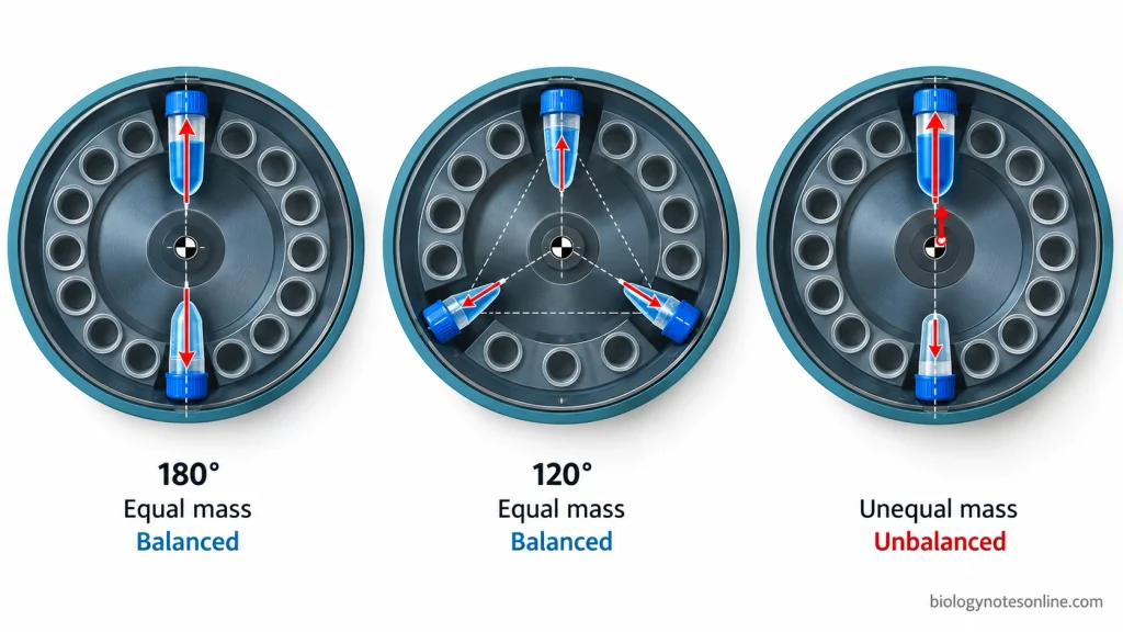
Symmetrical Distribution of Mass
Symmetrical distribution of mass involves placing the tubes around the rotor in positions where their forces are balanced. When two tubes having equal mass are placed directly opposite to each other (180° apart) at the same distance from the centre, the forces act in opposite directions. They cancel each other. Three tubes can also produce a balanced arrangement when they have equal loaded mass and are placed at an angle of 120° from each other. This forms an equilateral triangle around the centre of rotation.
An even number of tubes does not always produce a balanced load. The position of the tubes also affects the balance. Tubes containing equal volumes of liquid may have different masses due to differences in the density of the liquids. Sometimes the arrangement may appear symmetrical, but the opposing tubes have different masses which produces an imbalance.
Role of Rotor Geometry in Balancing
The geometry of the rotor determines the position of the tubes and their radial distance from the axis of rotation. Equal masses placed at different distances from the centre produce different centrifugal forces. The mass distribution within each loaded tube is also considered during balancing. Two opposing tubes may have the same total mass but different centres of gravity, which can affect the dynamic balance of the rotor.
In a swinging-bucket rotor, the load must also be balanced around the pivot axis of each bucket.
Rotors having equally spaced positions may allow opposing pairs or groups of three tubes to form a geometrically balanced arrangement. But these arrangements are not permitted in every rotor. The permitted loading pattern depends on the design of the rotor, available tube positions and the maximum loading limits specified by the manufacturer.
Centrifuge Balancing Procedure
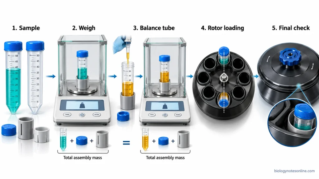
Selection of Suitable Centrifuge Tubes
- First, check the centrifuge rotor and the sample containers before use. Examine the rotor, tubes and buckets for cracks, corrosion or any other damage. The rotor cavities and centrifuge spindle must be clean and dry.
- Select the suitable centrifuge tubes depending on the type of rotor and the sample being centrifuged. The tubes may have conical, round or flat bottoms, depending on the rotor design. The tube material should be compatible with the sample and must withstand the required centrifugation speed, temperature and centrifugal force. The manufacturer’s specifications for the tubes and rotor are followed.
- Use the appropriate caps, adapters and tube holders when required. The tubes should fit properly inside the rotor cavities or adapters. Damaged or poorly fitting tubes must not be used.
Weighing and Matching Tube Masses
- Fill the sample tubes with the required volume of liquid. The liquid level must be within the filling limits specified by the manufacturer. Close the caps and clean the outer surface of the tubes before weighing.
- Each loaded tube is weighed using a laboratory balance. The mass of the complete assembly is measured, including the sample, tube, cap and sealing components. Adapters or buckets are also included when they form part of the assembly being balanced. Record the mass of each assembly.
- Compare the mass of the tubes or assemblies which will be placed opposite to each other in the rotor. The masses must be matched within the balancing tolerance specified by the manufacturer. This tolerance varies with the type of rotor and centrifuge. Equal liquid levels alone are not sufficient for balancing.
Preparation of Balance Tubes
- If there is no matching sample tube, an additional balance tube is prepared. It is used as a counterbalance. The balance tube should have the same type, size and shape as the sample tube, with a compatible cap and adapter.
- Add a suitable liquid into the balance tube. Water can be used for many aqueous samples if it is compatible with the tube and balancing conditions. In the case of liquids having higher density, a balancing liquid of similar density may be required. Equal volumes of different liquids may not have equal masses.
- The prepared balance tube is then weighed along with its cap and other required components. Add or remove the balancing liquid until the mass matches the sample tube within the permitted tolerance. The liquid should also remain within the recommended filling limits of the tube.
Arrangement of Tubes in the Rotor
- Check the rotor loading diagram given by the manufacturer and select the permitted arrangement of tubes. In rotors which allow opposing pairs, two tubes having equal loaded mass are placed directly opposite to each other (180° apart). Some rotors also allow three equally loaded tubes at an angle of 120° from each other. The permitted arrangement varies depending on the rotor design.
- Place the sample tubes and balance tubes in their assigned positions. All the tubes must be properly seated inside the rotor cavities or adapters. An even number of tubes does not always produce a balanced arrangement.
- In a swinging-bucket rotor, install all the buckets required by the manufacturer. Empty buckets are also installed where specified. The opposing buckets, caps and adapters should be properly matched. The load must be balanced around the axis of rotation as well as the pivot axis of the buckets. Check that the buckets are seated correctly and can swing freely.
Final Balancing Check Before Centrifugation
- After loading the tubes, check their positions again with the permitted loading pattern. There should not be any incorrectly placed or unmatched tube assemblies. The complete mass of each loaded compartment should also remain within the manufacturer’s specified limit.
- Make sure the tube caps, safety cups and rotor lid are properly secured. The seals or O-rings are also examined where present. Check that the rotor is correctly seated and attached to the centrifuge spindle. In the case of swinging-bucket rotors, the placement of buckets and adapters is checked.
- Before starting the centrifuge, verify the maximum permitted speed, sample density and operating conditions of the selected rotor and tubes. Close and secure the centrifuge lid. During the initial rotation, observe the centrifuge for any unusual vibration or noise. If excessive vibration occurs, stop the centrifuge. Allow the rotor to stop completely before checking the load.
Balancing a Fixed-Angle Rotor
Balancing Opposite Tube Positions
- In a fixed-angle rotor, the tubes remain at a fixed angle inside the rotor bores. First, check the number of tube positions and the loading pattern given in the rotor manual.
- Place two tubes having equal loaded mass directly opposite to each other (180° apart). The tubes should be of the same type, with suitable caps and adapters. In rotors requiring opposing pairs, the tubes are arranged in pairs across the centre of rotation.
- The mass of the complete tube assembly, including the sample, tube, cap and required adapter, is considered while balancing the opposite positions. Equal volumes of liquid may not have equal masses.
- If only one sample tube is available, prepare an additional balance tube. It is placed directly opposite to the sample tube. The mass of the balance tube is adjusted to match the sample tube within the permitted balancing tolerance.
Balancing Partial Rotor Loads
- A partial rotor load is used when all the tube positions are not filled. In rotors requiring opposite pairs, the tubes are placed in matched pairs and the remaining positions are left empty where permitted. For example, the Eppendorf F-34-6-38 is a fixed-angle rotor having six tube positions. Its centrifuge manual specifies that the tubes are loaded opposite to each other in pairs.
- Three tubes having equal loaded mass can also form a geometrically balanced arrangement when they are placed at an angle of 120° from each other. A rotor having six equally spaced positions can geometrically accommodate such an arrangement by using alternate positions. But not all six-position rotors permit three-tube loading. The arrangement must be approved by the manufacturer. In rotors which require opposing pairs, an odd number of sample tubes needs an additional matched balance tube to complete the permitted arrangement.
- Before starting the centrifuge, check the partially loaded rotor with the manufacturer’s loading diagram. Make sure the tubes are placed in the correct positions and the mass of each loaded assembly is within the permitted limit. The appropriate rotor lid is then attached and secured.
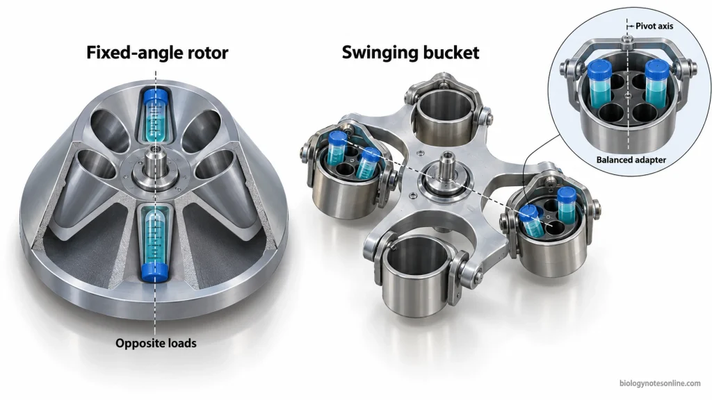
Balancing a Swinging-Bucket Rotor
Balancing Opposing Buckets
- In a swinging-bucket rotor, the buckets are attached to the rotor by pivot pins and swing outward during centrifugation. The load must be balanced around the centre of rotation as well as the pivot axis of each bucket.
- Place the loaded buckets in opposite positions according to the rotor loading diagram given by the manufacturer. The opposing buckets should have nearly equal masses within the specified balancing tolerance. The mass of the complete assembly is considered, including the bucket, sample tubes, adapters, caps and other required components.
- Use the same type of tubes, adapters and other accessories in opposing buckets. The sample tubes should contain liquids of similar density and their loaded masses must be properly matched.
- All the buckets required by the manufacturer must be installed, even when some of them do not contain samples. For example, in a four-position rotor which requires all four buckets, two loaded buckets are placed opposite to each other and the remaining two buckets are also installed. Some rotors require empty adapters or other specified “blank loads” inside the unused buckets. The permitted arrangement depends on the rotor design.
- Check that the buckets are properly seated on their pivot pins and can swing freely. The bucket caps or covers must be secured where required.
Balancing Tubes Within Each Bucket
- The tubes inside each bucket are also arranged in a balanced pattern. In a swinging-bucket rotor, each bucket rotates around its own pivot axis while moving outward. The weight must be properly distributed on both sides of this axis.
- Place the sample tubes into suitable adapters or tube holders. When all the positions are not filled, the tubes are arranged symmetrically around the pivot axis of the bucket. The opposing buckets should also have a corresponding arrangement of tubes.
- If the tubes cannot be arranged symmetrically, additional balance tubes may be used in the permitted positions. They are prepared with a suitable balancing liquid and adjusted to the required mass. The balancing arrangement must follow the manufacturer’s instructions.
- A bucket may have the same total mass as its opposing bucket but still be unbalanced around its own pivot axis. The bucket may not swing into the proper horizontal position during centrifugation. This can produce additional stress on the buckets, adapters and tubes, increasing the risk of breakage or rotor imbalance. It may also affect the separation of samples.
Centrifuge Balancing Charts for Different Tube Numbers
The centrifuge balancing arrangement varies depending on the number of sample tubes and the available positions in the rotor. Two or more tubes can be arranged in opposite pairs or other symmetrical groups. An additional balance tube is used when the required arrangement cannot be formed with the available sample tubes.
The following examples are based on ideal 12-position and 24-position fixed-angle rotors having equally spaced tube positions. These are geometrically balanced arrangements. The permitted loading pattern must be checked in the manufacturer’s rotor manual before centrifugation.
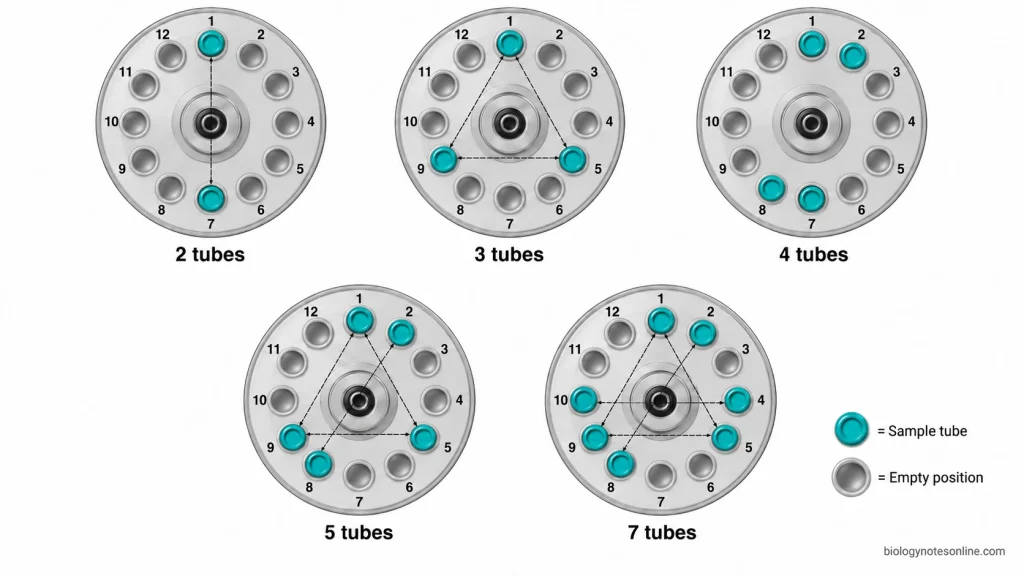
Balancing 2 and 4 Tubes
- For 2 tubes, place the tubes directly opposite to each other (180° apart). Both tubes must have equal loaded mass within the permitted balancing tolerance. In a 24-position rotor, positions 1 and 13 form an opposite pair.
- When 4 tubes are used, they can be placed in two opposing pairs. Each pair should have matching masses. For example, positions 1, 2, 13 and 14 form two balanced pairs in a 24-position rotor. The masses of the two pairs need not be equal to each other, provided each opposing pair is balanced.
Balancing 3 Tubes
- Three tubes having equal loaded mass can be balanced by placing them at 120° intervals around the centre of rotation. This forms a triangular arrangement. In an equally spaced 24-position rotor, positions 1, 9 and 17 produce this arrangement.
- If the rotor does not permit three-tube loading, an additional balance tube is required for a permitted paired arrangement. For example, three sample tubes can be placed in positions 1, 2 and 13, with the balance tube in position 14 of a compatible 24-position rotor. This forms two opposing pairs.
Balancing 5 Tubes
- Five tubes may be balanced by combining a group of three tubes with one opposing pair in a rotor which permits this arrangement. The three tubes are placed at 120° intervals and the other two tubes are placed opposite to each other. In a 24-position rotor, positions 1, 9 and 17 form the group of three, whereas positions 2 and 14 form the opposite pair.
- Some rotors require an additional balance tube when five samples are used. In this case, six loaded positions can be arranged into three opposing pairs. For example, five sample tubes placed in positions 1, 2, 3, 13 and 14 can be balanced by adding a matched tube in position 15 of a compatible 24-position rotor.
Balancing 7 Tubes
- Seven tubes can form a geometrically balanced arrangement by combining three tubes at 120° intervals with two opposing pairs. This arrangement is possible in a compatible 24-position rotor using positions 1, 9 and 17 for the group of three, positions 2 and 14 for the first pair and positions 3 and 15 for the second pair. The tubes within each group must have matching loaded masses.
- In rotors requiring paired loading, 7 sample tubes need one additional balance tube to make four opposing pairs. For example, the samples may occupy positions 1, 2, 3, 4, 13, 14 and 15, with the balance tube in position 16 of a compatible 24-position rotor. The added tube is matched in mass with the sample tube opposite to it.
Balancing Tubes in 12- and 24-Position Rotors
The following chart shows geometrically balanced tube arrangements for ideal rotors having 12 or 24 equally spaced positions. The positions are numbered clockwise, beginning from position 1 at the top of the rotor.
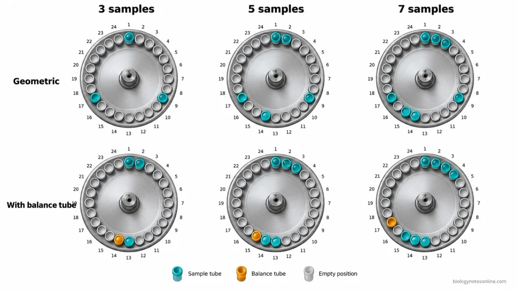
| Sample tubes | 12-position rotor | 24-position rotor | Extra balance tubes |
|---|---|---|---|
| 2 | 1, 7 | 1, 13 | 0 |
| 3 | 1, 5, 9 | 1, 9, 17 | 0 if permitted, otherwise 1 for paired loading |
| 4 | 1, 2, 7, 8 | 1, 2, 13, 14 | 0 |
| 5 | 1, 2, 5, 8, 9 | 1, 2, 9, 14, 17 | 0 if permitted, otherwise 1 |
| 7 | 1, 2, 4, 5, 8, 9, 10 | 1, 2, 3, 9, 14, 15, 17 | 0 if permitted, otherwise 1 |
For 12-position rotors which require loading in opposite pairs, the following alternative arrangements can be used if approved by the manufacturer-
- 3 samples: Positions 1, 2 and 7, with a balance tube in position 8.
- 5 samples: Positions 1, 2, 3, 7 and 8, with a balance tube in position 9.
- 7 samples: Positions 1, 2, 3, 4, 7, 8 and 9, with a balance tube in position 10.
The 24-position rotor allows more equally spaced positions, but this does not mean all geometric arrangements are permitted. Some rotor manuals allow special partial-load patterns while others require matched opposing pairs.
For example, the Thermo Scientific TFT-80.2, a 12-position fixed-angle rotor, permits a specified five-tube arrangement. The T-1270 rotor has different instructions and requires an additional dummy tube when five or seven samples are used. The approved position chart and balancing tolerance of the particular rotor must be followed.
Identifying and Correcting Centrifuge Imbalance
Signs of an Unbalanced Centrifuge
- Excessive vibration may occur when the centrifuge load is not balanced properly. The rotor may begin to shake or wobble as the speed increases. A slight vibration during acceleration or deceleration may be normal in some centrifuges. But strong vibration is an abnormal condition.
- An unbalanced centrifuge may produce unusual rattling, knocking or loud noise during rotation. Such noises may also occur due to mechanical problems.
- Sometimes the centrifuge shakes excessively and moves from its normal position on the laboratory bench. This is known as centrifuge walking.
- Some centrifuges are equipped with an imbalance detection system which produces a warning message or error code when excessive imbalance is detected. The centrifuge may stop automatically. This feature is not present in every centrifuge. An imbalance detector does not correct the improperly balanced load.
- The abnormal vibration may also be caused by improper rotor seating, damaged components or worn bearings. It is not always due to incorrect balancing of sample tubes.
Steps to Correct Centrifuge Imbalance
- When excessive vibration, unusual noise or an imbalance warning is observed, stop the centrifuge immediately according to the manufacturer’s instructions. Do not open the centrifuge lid while the rotor is moving.
- Allow the rotor to stop completely before opening the lid. If tube breakage or sample leakage is suspected, the centrifuge should be kept closed and the laboratory emergency procedure is followed. In such cases, a waiting period may be required for hazardous aerosols to settle.
- Check the positions of the sample tubes inside the rotor. The tubes must be placed according to the manufacturer-approved loading pattern. Examine the opposing positions and check whether the partially loaded rotor follows the permitted arrangement.
- Remove the tubes and weigh them using a laboratory balance. The mass of the complete loaded assembly is measured, including the sample, tube, cap and other required accessories. Compare the masses of the opposing assemblies. They should be matched within the balancing tolerance specified by the manufacturer. If required, prepare an additional balance tube or adjust the mass of the existing tubes.
- The rotor, tubes, adapters and buckets are examined for damage or improper seating. Check whether the rotor is properly attached to the centrifuge spindle. In the case of a swinging-bucket rotor, the buckets should be correctly placed and must swing freely. The tube caps and rotor lid are also checked for proper closure.
- Examine the centrifuge chamber for any broken tubes, sample leakage or damage. Damaged components must not be used again. If any sample has spilled or contamination is suspected, follow the laboratory safety procedure for handling the spill.
- After correcting the load, the centrifuge may be operated again according to the instructions for that particular model, provided no damage is found. If the excessive vibration, unusual noise or imbalance warning continues, the centrifuge must be removed from service. It should be labelled as unfit for use. The equipment must be examined by qualified service personnel before further operation.
Importance of Centrifuge Balancing
- Centrifuge balancing maintains the proper distribution of mass around the rotor. It reduces excessive vibration during centrifugation.
- The rotor, spindle and bearings are protected from additional mechanical stress by balancing the load properly, which helps to prevent damage to the centrifuge.
- It reduces the chances of tube breakage or leakage. This helps to prevent the loss of samples.
- The risk of rotor failure is reduced by balancing the centrifuge. It also reduces the risk of injury to laboratory workers.
- In the case of infectious samples, proper balancing reduces the chances of tube breakage and the release of hazardous aerosols.
Consequences of Uneven Centrifuge Balancing
- An unevenly balanced rotor produces excessive vibration during centrifugation. The centrifuge may shake, produce loud noise or move from its position.
- The rotor, spindle and bearings are subjected to additional mechanical stress due to the unbalanced load. It may damage these parts and reduce the service life of the centrifuge.
- In severe cases, rotor failure may occur during centrifugation. The broken rotor parts can damage the centrifuge and may cause serious injury to laboratory workers.
- The centrifuge tubes may crack or break, resulting in sample leakage and loss. Spilled samples may also contaminate the rotor and centrifuge chamber.
- When tubes containing infectious materials break during centrifugation, hazardous aerosols may be produced. These aerosols may expose laboratory workers to infectious agents.
- Some centrifuges have an imbalance detection system which automatically stops the centrifuge when excessive imbalance is detected. This interrupts the centrifugation process.
References
- Babenko, A., & Lavrenko, I. (2024). The influence of imbalances on the dynamic characteristics of the laboratory centrifuge HERMLE Z306. Mechanics and Advanced Technologies, 8(1), 62–72. https://doi.org/10.20535/2521-1943.2024.8.1(100).294820
- Clark, D. E. (2001). Safety and the laboratory centrifuge. Chemical Health & Safety, 8(6), 7–13. https://doi.org/10.1016/S1074-9098(01)00263-5
- Ford, T. C., & Graham, J. M. (1991). An introduction to centrifugation. BIOS Scientific Publishers. https://books.google.com/books?id=zG9OAQAAIAAJ
- Graham, J. M. (2001). Biological centrifugation. Garland Science. https://www.routledge.com/Biological-Centrifugation/Graham/p/book/9781859960370
- Hambleton, P., & DeDonato, G. (1992). Protecting researchers from instrument biohazards. BioTechniques, 13(3), 450–453. https://pubmed.ncbi.nlm.nih.gov/1389178/
- Harper, G. J. (1981). Contamination of the environment by special purpose centrifuges used in clinical laboratories. Journal of Clinical Pathology, 34(10), 1114–1123. https://doi.org/10.1136/jcp.34.10.1114
- Rickwood, D. (Ed.). (1992). Preparative centrifugation: A practical approach. Oxford University Press. https://doi.org/10.1093/oso/9780199632084.001.0001
- Roth, H., & Rickwood, D. (1992). Centrifuges and rotors. In D. Rickwood (Ed.), Preparative centrifugation: A practical approach (pp. 43–76). Oxford University Press. https://doi.org/10.1093/oso/9780199632084.003.0002
- Spragg, S. P., & Steensgaard, J. (1992). Theoretical aspects of practical centrifugation. In D. Rickwood (Ed.), Preparative centrifugation: A practical approach (pp. 1–42). Oxford University Press. https://doi.org/10.1093/oso/9780199632084.003.0001