What is Polarizing Microscope?
- A Polarizing Microscope (also called Petrographic Microscope) is a compound optical instrument that uses polarized light to study anisotropic materials.
- It is mostly used in geology, materials science, and forensic work for seeing crystal structure that normal microscope cannot show.
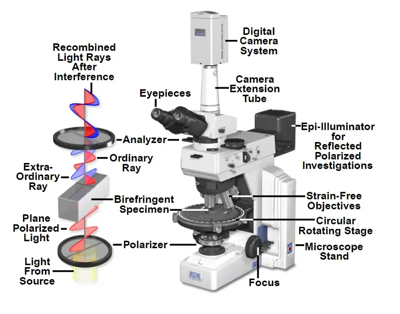
- The device works by passing unpolarized light by a polarizer, which converts it into plane-polarized light that vibrates in single direction.
- When that light enters a mineral grain or sample, it may split into two rays — the fast ray and the slow ray — a thing called birefringence or double refraction.
- These two rays travel with different speed; after combining by analyzer filter, they create interference colors that show internal structure and orientation of crystals.
- The microscope contains several special parts – polarizer, analyzer, rotating stage, strain-free objectives, Bertrand lens, and accessory plates (1λ, quartz wedge) etc.
- It can work in two light modes: Plane-Polarized Light (PPL) when only lower polarizer used, and Cross-Polarized Light (XPL) when both polarizer/analyzer are crossed at 90°.
- Under PPL, things like color, relief, pleochroism, and cleavage are seen, while XPL shows interference colors, extinction, and twinning.
- It helps to identify minerals, determine optic sign, extinction angle, and even estimate the 2V angle of biaxial crystals.
- Because light behavior is different in isotropic vs anisotropic materials, this microscope can separate minerals like quartz, feldspar, biotite, etc. accurately.
- Its advantage is that it’s non-destructive, gives both qualitative and quantitative optical data, but it need very thin section (≈30 µm) and proper calibration to work correctly.
- The Polarized Light Microscope (PLM) history start early 19th century, when light behavior in crystals first become interesting to scientists.
- The first polarizing prism was invented by William Nicol in 1829, it used special calcite prism (Nicol Prism) that split light into two polarized rays.
- Around 1815, Sir David Brewster had already described the phenomenon of polarization by reflection, his ideas later shaped optical instruments.
- After few years, Henry Fox Talbot (1834) experimented by using polarized light for studying minerals; he gave more practical approach though instrument was still crude.
- The real breakthrough came with Henry Clifton Sorby (1858), who first applied this idea to thin rock sections for seeing mineral texture under microscope.
- Sorby’s demonstration actually made petrography a scientific discipline, because rocks could now be studied microscopically and classified by mineral content.
- Through late 1800s, the instrument evolved — addition of rotating stage, crossed polarizers, and Bertrand lens allowed interference figures to be seen clearly.
- By early 20th century, polarizing microscopes became essential in geology, later adopted in materials science and biology for fiber, polymer and tissue studies.
- Modern versions still use the same Nicol concept but with improved filters (like polyvinyl alcohol iodine films) instead of calcite prisms.
- Thus, from simple prism experiments to a complex analytical instrument, PLM development show how physics and geology got linked by light itself.
Principles of Polarized Light Microscopes
- The Polarized Light Microscope (PLM) works on the principle of how light waves interact with materials that have ordered internal structure, called anisotropic substances.
- Normal light is unpolarized – it vibrates in many directions. After passing through polarizer, it becomes plane-polarized light, vibrating in one single plane.
- When this polarized beam goes by a crystal, if the mineral is anisotropic, the light is split into two rays (a fast ray and a slow ray).
- This phenomenon known as Double Refraction or Birefringence; it occurs because the refractive index (n) of mineral varies with light direction.
- The velocity difference between those two rays cause a retardation (Δ) — mathematically written as Δ = t(nslow – nfast), where t is sample thickness (usually 0.03 mm).
- As both rays emerge, they combine again by the analyzer filter (crossed at 90° to the polarizer). Some wavelengths cancel, some reinforce, forming bright Interference Colors.
- These colors depend on birefringence, sample thickness, and orientation. They’re used to estimate optical properties through a Michel-Lévy Chart.
- Under Plane-Polarized Light (PPL), only lower polarizer is used, letting observer note color, pleochroism, relief and cleavage.
- When analyzer inserted (Cross-Polarized Light – XPL), field turns dark for isotropic minerals, while anisotropic ones appear colorful, changing every 90° rotation.
- The optical extinction happens when the mineral’s vibration directions align parallel with those of polarizer and analyzer—light fully blocked, appearing black.
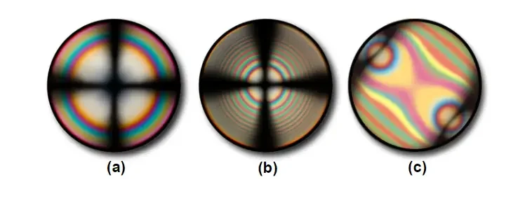
- For advanced optics, a Bertrand lens and conoscopic system used to see interference figures that help identify optic sign (positive or negative) and 2V angle.
- In short, PLM converts invisible structural anisotropy into visible optical contrast by controlled manipulation of polarized light—light itself becomes the probe.
The Light Path and Image Formation of Polarized Light Microscopes
- In PLM, the light path begins from the illuminator, normally a small halogen lamp, giving unpolarized white light.
- This light travels upward by condenser lens and reach the lower polarizer, where it get converted into plane-polarized light (vibrating in one single plane).
- After that, the beam passes by the specimen placed on rotating stage. If the sample is anisotropic, it splits into two components – the fast ray and slow ray.
- Because both rays move with different velocity (due to different refractive indices), they become out of phase, creating something called Optical Path Difference (Δ).
- This retardation is mathematically expressed as Δ = t(nslow – nfast); where t means thickness of section (usually 30 µm), and n is refractive index difference.
- The two rays exit the specimen still vibrating perpendicular to each other. They next pass into the objective lens, which form intermediate image for viewing.
- Above this, the analyzer — another polarizing filter set at 90° — intercepts both rays and lets only the vibration components parallel to its plane go through.
- Inside analyzer, these two rays interfere: some wavelengths cancel (destructive interference), others combine (constructive interference), giving visible interference colors.
- These colors vary with birefringence, orientation, and thickness, producing the bright patterns seen under crossed polars.
- The eyepiece (ocular) magnifies that final image, sometimes containing crosshairs for measurement of extinction angles or crystal directions.
- When the analyzer is removed (only polarizer used), the light path simpler, showing color, relief, pleochroism, and cleavage — this condition is Plane-Polarized Light (PPL).
- With both polarizer and analyzer inserted and crossed, the configuration called Crossed Polars (XPL), producing dark background where isotropic minerals appear extinct.
- For advanced optical study, a Bertrand lens and conoscopic lens used together so the interference figure at back focal plane of objective can be observed.
- This figure gives data about optic sign (positive/negative) and 2V angle, confirming mineral type.
- So the PLM image forms step-by-step — from simple light vibration to complex interference pattern — all controlled carefully by polarizing components.
Parts of a Polarized Light Microscope
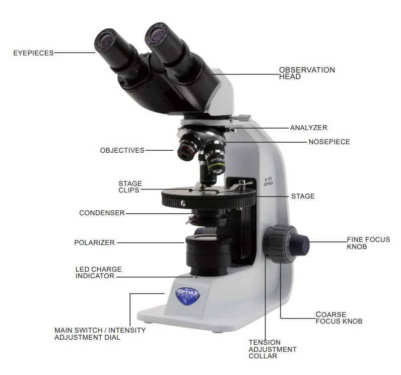
1. Light Source – usually a halogen bulb that gives bright white light; it must be stable so the color don’t change by heating or voltage drift.
2. Condenser – placed below the stage, it focuses light onto specimen. It has aperture diaphragm and field diaphragm; both help adjust illumination (contrast/resolution).
3. Polarizer – a special filter fixed below the stage, converts unpolarized light into plane-polarized light vibrating in single direction. Often made of polyvinyl alcohol film with iodine.
4. Stage – a circular rotating stage (360°) having degree markings, used for observing optical changes on rotation. It also has centering screws for alignment.
5. Objectives – high quality strain-free lenses, because glass strain may create false birefringence. Common magnifications 4×, 10×, 40×, and 60× (sometimes oil immersion).
6. Analyzer – second polarizing filter above objective lenses. It’s placed at 90° to polarizer (crossed position), can be inserted/removed easily from the light path.
7. Oculars / Eyepieces – lenses where observer sees final image. One eyepiece often has crosshairs, helping measure extinction angle or align crystal axis.
8. Bertrand Lens – a small movable lens inside the tube, used with conoscopic lens for viewing interference figures at back focal plane.
9. Accessory Slot – located between objective and analyzer; used for inserting compensators like full-wave plate (1λ), quarter-wave plate (¼λ), or quartz wedge for measuring retardation.
10. Conoscopic (Condenser) Lens – focuses the light as cone beam for interference figure observation, essential for conoscopic mode.
11. Mirror / Reflector – sometimes added in older microscopes for directing external light, now replaced by built-in illuminator.
12. Coarse & Fine Focus Knobs – help bring image in focus precisely; fine focus used during high magnification or conoscopic view.
13. Mechanical Stage Clips – keep thin section slide fixed during rotation or focusing.
14. Diaphragms – two main types: Field diaphragm (controls illuminated area) and Aperture diaphragm (controls cone angle / numerical aperture).
15. Frame & Arm – rigid body holding optical parts together, usually heavy for stability (metal or alloy).
16. Power Supply & Rheostat – controls lamp brightness; stable voltage is needed for true color observation.
Basic Properties of Polarized Light
Light is a form of electromagnetic radiation, it travels as waves having both electric and magnetic fields at right angle to each other.
In normal condition, these waves vibrate in many directions — that’s called Unpolarized Light.
When the light pass by a polarizing filter, only the waves vibrating in one single plane are allowed to go through; this type is called Plane-Polarized Light (PPL).
The Plane of Polarization means the direction in which the electric vector vibrates after passing by polarizer.
When polarized light enter an anisotropic crystal, it is split into two rays — ordinary (fast) and extraordinary (slow) ray.
These rays travel with different velocity (v) inside crystal due to change of refractive index (n) with direction.
The Refractive Index (n) is defined as ratio of velocity of light in vacuum (c) to its velocity in material (v). So, n = c/v.
Because of difference in velocity, a phase difference occurs between rays, producing a retardation (Δ) = t(nslow – nfast) (t = thickness of sample).
The color or brightness seen under crossed polars depends directly on this retardation and mineral’s birefringence (δ) value.
When the vibration directions of crystal align parallel to polarizer/analyzer, total extinction occurs — called Extinction Position.
If mineral is isotropic, it has single refractive index and light travels same speed in all directions, so it always appear black in crossed polars.
If mineral is anisotropic, refractive index change with direction and produces interference colors during rotation.
Interference Colors arise because the fast and slow rays interfere after analyzer — some wavelengths cancel (destructive), others reinforce (constructive).
These optical properties — polarization, birefringence, interference, and extinction — form base principle for using polarized microscope in mineral identification.
Operating Procedure of Polarized Light Microscope
- Turning On the Light Source – The built-in halogen bulb is switched on first, brightness adjusted by rheostat till illumination look uniform. Sometimes it’s not steady at start, so wait a minute.
- Placing of Sample Slide – The thin section (around 0.03 mm) is positioned on rotating stage, kept firm using the small clips so it doesn’t slip by rotation.
- Selecting Objective Lens – Observation usually begin with low-power lens (4×/10×). Higher magnification used later when grain of interest located, that help avoid missing it.
- Focusing the Image – Coarse focus knob used first, after that fine focus slightly adjusted until both eyes see same clear field. The diopter ring can be twisted for each eye (sometimes people forget that step).
- Setting Up Köhler-like Illumination –
- Field diaphragm closed, its polygon edge focused by condenser knob.
- Image centered using condenser screws (it must be central).
- Field diaphragm opened slowly until edge vanish outside view.
- Aperture diaphragm opened about 70 – 80 % of objective NA for best contrast; this balance not fixed, depend by mineral brightness.
- Centering the Stage – A single distinct grain is chosen, centered under crosshair. Stage rotated fully, and if grain moves in small circle, centering screws adjusted half-way, again rotated, until it stays.
- Checking Parcentering of Objectives – Once stage centered, switch to each objective lens. If image shift, objective centering screws turned little. It keeps every lens sharing same axis.
- Observation in Plane-Polarized Light (PPL) –
- Analyzer removed.
- Features like color, pleochroism, cleavage, and relief are recorded.
- The Becke Line test done by lowering stage—bright halo moves into higher-refractive-index side.
- Observation under Cross-Polarized Light (XPL) –
- Analyzer inserted, the field becomes dark background.
- Stage rotated; isotropic minerals remain black always, anisotropic show color flashes every 90°.
- Observe interference colors, birefringence, extinction, twinning and zoning, etc.
- Measurement of Extinction Angle – Long axis or cleavage aligned with eyepiece crosshair; the stage rotated to extinction and reading noted. Difference of both positions give the extinction angle.
- Testing Sign of Elongation – For elongate grain, its axis set at 45° to crosshair (NE–SW). Insert full-wave plate (1λ).
- If color add up (gray → blue), grain is length-slow.
- If color drop (gray → yellow), it’s length-fast.
- Conoscopic Mode (Interference Figure) –
- Conoscopic lens engaged, and Bertrand lens inserted.
- A centered grain viewed gives optic axis or acute bisectrix figure.
- After inserting 1λ plate again, NE/SW color shift (blue = optic positive; yellow = optic negative).
- Recording & Identification – All observed optical characters are written carefully—sometimes twice—to avoid mis-identifying mineral later. Comparison done by standard optical data charts.
- After Operation / Maintenance – Slide removed, lamp switched off, and microscope left to cool down. Lens cleaned by tissue (not rough cloth), cover placed. Never touch bulb bare-hand or it may prevail burning mark.
Applications of Polarized Light Microscope
- In Geology and Petrology –The PLM mainly applied for mineral identification in thin sections of rocks. Minerals like quartz, feldspar, and biotite are distinguished by their color, interference pattern and birefringence. Rock textures, crystal habits, and alteration stages are also studied — this helps to interpret how that rock formed or got deformed later.
- In Mineralogy Education / Research –Used in teaching labs to train students to recognize optical characters. The rotating stage demonstration show how extinction and pleochroism change with orientation; quite visual and memorable.
- In Materials Science and Metallurgy –The instrument used for examining crystalline polymers, ceramics, and metal alloys. It reveal internal stress lines and grain boundaries which invisible by normal microscope. Residual stress in glass and composite materials are often analyzed following ASTM C 978 standard.
- In Polymer Chemistry– Polarized microscope used to visualize spherulites in semicrystalline polymers, their growth form and direction can be measured. This helps in knowing cooling rate and molecular orientation — otherwise that structure stays hidden.
- In Biological and Medical Fields– PLM applied to view collagen fibers, muscle filament arrangement, and spindle microtubules in dividing cells. It’s very helpful for studying unstained living tissues since contrast appear naturally from molecular order.
- In Reproductive Medicine – Modern IVF labs use it for locating meiotic spindle in oocytes without staining. That allow safe micromanipulation during enucleation or fertilization, improving success of procedure.
- In Forensic Science – This microscope used to compare textile fibers, hair, and dust particles. It gives optical fingerprint; analysts can tell whether fibers from crime scene match a suspect garment. Quick, non-destructive, and quite trusty method.
- In Industrial Quality Control– Used to monitor orientation defects or strain birefringence in transparent plastics, films, or crystals. Some factories keep a PLM near production line for spot checking — simple but effective.
- In Gemology– Applied to identify gems that are doubly refracting, to separate synthetic stones from natural ones by observing interference figures and optic sign.
- In Environmental and Soil Studies– Thin soil sections observed to see grain fabric, micro-fossils and mineral weathering pattern. This help determine soil genesis and contamination level.
Advantages of Polarized Light Microscope
Here is the some Advantages of Polarized Light Microscope;
- Enhanced Image Contrast –Polarized light allows clear visibility of birefringent materials that look almost invisible in normal brightfield view. It’s especially useful for transparent crystals or fibers.
- Detailed Structural Information –Internal arrangement of molecules, crystal orientation, and even strain pattern become visible. This gives more than just shape — it reveals inner order too.
- Non-Destructive Method–Samples stay intact, no staining or chemical treatment required. The same thin section can be re-used again for years (if handled carefully).
- Colorful and Informative Output– The interference colors created by birefringence not only look beautiful, they indicate retardation value — directly linked with mineral’s optical property.
- Quantitative & Qualitative Data Together –Both types of information obtained: extinction angle, refractive index, birefringence (quantitative) and optical character (qualitative).
- Real-Time Observation– It’s possible to watch dynamic changes (like melting, recrystallization, or deformation) happening under heat stage. The color change shows it instantly.
- Applicable Across Many Disciplines– Same instrument can used in geology, materials science, forensics, and biology, making it quite versatile / multipurpose.
- Simple Setup & Direct Observation –Once the illumination is adjusted properly, results seen directly through eyepiece — no complex image processing or external computer required.
- Cost-Effective Tool– Compared with electron microscopy, PLM is cheaper, easier maintenance, and needs only normal power supply. So it’s widely adopted in teaching labs.
- Helpful in Stress and Defect Analysis– The birefringent pattern in glass, plastic or polymer can show where stress exist inside, allowing engineers to adjust production steps.
- High Reliability of Mineral Identification– When procedure followed correctly (using PPL, XPL, conoscopic view), the mineral identity can be confirmed precisely. The repeatability of results is sturdy and hardy.
- Aesthetic Educational Value– The colorful interference pattern attracts learners; helps students remember optical properties easily, sometimes more effective than text-book explanation.
Limitations
Here is the some Limitations of Polarized Light Microscope
- Restricted to Birefringent Materials– The PLM works only for anisotropic substances. Isotropic materials (like glass, cubic crystals, liquids) always appear black under crossed polars, giving no usable data.
- Limited Magnification Power– Since it’s still an optical microscope, its resolution limited by wavelength of visible light (≈200 nm). So it can’t see atomic structure or sub-grain boundaries clearly.
- Sample Preparation Complexity– Preparing thin section (30 µm) or grain mount need precision grinding, polishing, mounting. The process is slow and require experienced hands, else optical results become wrong.
- Optical Strain Problems– Even small strain in objective lens glass or cover slip may introduce false birefringence. That can confuse user badly, so strain-free optics are must, which costly.
- Need for Skilled Operator– Interpretation of interference colors, extinction angle, and optic sign demand proper training. A beginner often misread second-order color as first-order one.
- Limited Depth of Field– Thick or uneven samples can’t be observed properly because only small portion stay in focus, others become blurry.
- No Chemical Composition Data –PLM reveals optical behavior, not elemental composition. For full identification it’s often combined with XRD or SEM-EDS analysis.
- Light Intensity & Color Temperature Dependence – When lamp voltage fluctuates, color seen by observer may shift. So interpretation of interference order can vary from one session to another.
- High Cost of Quality Components –True strain-free objectives, Bertrand lens, and precision rotating stage are expensive, not affordable for every small lab.
- Possibility of Misalignment –Miscentered stage or tilted analyzer cause wrong interference pattern. A small mechanical play prevail misreading of optic axis position.
- Time-Consuming for Multiple Samples –Each thin section must be focused, rotated, observed in both PPL and XPL, sometimes under conoscopic mode. For big collection it’s very time heavy.
- Not Suitable for Opaque Minerals– Completely opaque minerals can’t transmit light at all; they require reflected light microscopy, so PLM useless for them.
- Environmental Sensitivity – Humidity or fungal growth on optics affect clarity; even small dust gives rainbow fringes around grain, that distort observation.
Polarized Light Microscope Images

- https://microscopeinternational.com/optika-b-150p-brpl-binocular-led-polarizing-microscope-rechargeable/
- https://www.microscope.healthcare.nikon.com/products/polarizing-microscopes
- https://www.microscopyu.com/techniques/polarized-light/polarized-light-microscopy
- https://www.olympus-lifescience.com/en/microscope-resource/primer/techniques/polarized/configuration/
- https://www.microscopeworld.com/t-polarizing_microscopes.aspx
- https://www.microscope.com/specialty-microscopes/polarizing-microscopes
- https://www.azolifesciences.com/article/What-are-Polarized-Light-Microscopes-and-How-Do-They-Work.aspx
- https://www.sciencedirect.com/topics/chemistry/polarizing-microscopy
- https://meijitechno.com/meiji_old/polarizing_applications.htm
- https://www.news-medical.net/Life-Science-and-Laboratory/Polarizing-Microscopes
- https://zeiss-campus.magnet.fsu.edu/referencelibrary/polarizedlight.html
- https://www2.humboldt.edu/scimus/HSC.36-53/Descriptions/AOPolScp.htm
- https://www.optikamicroscopes.com/optikamicroscopes/product/pol-series/
- https://www.motic.com/As_Polarized_microscope/
- https://amscope.com/collections/polarizing-microscopes
- Text Highlighting: Select any text in the post content to highlight it
- Text Annotation: Select text and add comments with annotations
- Comment Management: Edit or delete your own comments
- Highlight Management: Remove your own highlights
How to use: Simply select any text in the post content above, and you'll see annotation options. Login here or create an account to get started.