Atomic force microscopy (AFM) is an imaging technique that can capture images at the nanoscale. It works like an electron microscope, but instead of imaging with light or electrons, it “feels” the surface it is trying to assess. A mechanical probe, like a very delicate fingertip, “scans” a sample and creates a map of the surface with a level of detail rarely achieved, even down to sub-nanometers. This level of precision exists because the microscope uses piezoelectric materials.
These materials simply expand/contract based on electrical pulses sent to them, meaning that the AFM probe can rest on or under a given surface at nanoscopic levels with unfathomable levels of imaging detail that would otherwise be impossible.
AFM emerged in the 1980s as an offshoot of the scanning tunneling microscope (STM) invented by researchers at IBM. STM revolutionized scientific imaging as we know it. The offspring that earned its parents a Nobel Prize imaged surfaces based on quantum physics. The limitation was that only conductive materials could be studied.
However, almost any material could be studied with AFM. So a spinoff was created. By the late 1980s, AFM was commercially available and applied in the field beyond the laboratory, revolutionizing understanding in materials science, biology, and beyond. It is the instrument of choice for anyone who wants to observe the unobservable.
What is an Atomic Force Microscope (AFM)?
An atomic force microscope is an example of a scanning probe microscope that scans a sample at the atomic level to generate an image (and potentially manipulate) of the surface. The interaction of the tip of the probe with the surface of the material results in the scanning and force measurement. The atomic force microscope produces a comprehensive image of the sample’s surface while simultaneously measuring its qualities, such as roughness. It serves as an effective diagnostic tool to understand the quality of all kinds of materials, including metals, semiconductors, polymers, and biomaterials.
The idea of a needle that can “read” and “write” at the atomic level was first conceived in the late 1950s and 1960s with the construction of a device by G. Binnig and H. Rohrer (who were awarded the Nobel Prize in Physics for this invention). However, it was not until several years later, in the mid-1980s, that a practical AFM was built by three separate teams: Gerd Binnig and Calvin Quate at IBM, Christopher Gerber and Art Heinrich at Stanford University, and Alain Marti and Michel Orrit at Leiden University. Since then, AFMs have expanded beyond their original uses and been adopted in a variety of fields, from materials science to nanoscience to biology, leading to the development of many other types of scanning probe microscopes, such as the scanning tunneling microscope and the scanning near-field optical microscope.
Principle of Atomic Force Microscope
An AFM microscope senses a surface by a micromachined silicon probe with a sharp tip. The probe moves linearly back and forth across the sample surface while sensing and creating an image. However, different operating methods achieve this task in different ways. There are two main operating modes. The first is contact mode and the second is dynamic or tapping mode.
AFM works on the principle of a nanoscale tip glued to a tiny cantilever that acts like a spring. A laser diode and a split photodetector are placed in place to detect the deflection of the cantilever. The deflection is caused by the tip-sample interaction and can be thought of as a force that the tip exerts on the sample like a spring. For example, in contact mode, the tip is pressed against the surface and an electronic feedback loop senses the force of the tip-sample interaction to stabilize the deflection as a raster scan is performed.
In tapping mode, the contact time between the sample surface (i.e. the sample) and the tip is reduced, saving both contact times, and in this state the cantilever is stimulated to oscillate at the driving frequency. The tip then moves up and down in a sinusoidal manner. This vertical sinusoidal movement is damped by attractive or repulsive forces. Unlike the contact mode, which has a feedback loop to maintain the quasi-static deflection, here the feedback loop maintains the amplitude of the tapping motion, which also generates a virtual image of the topography.
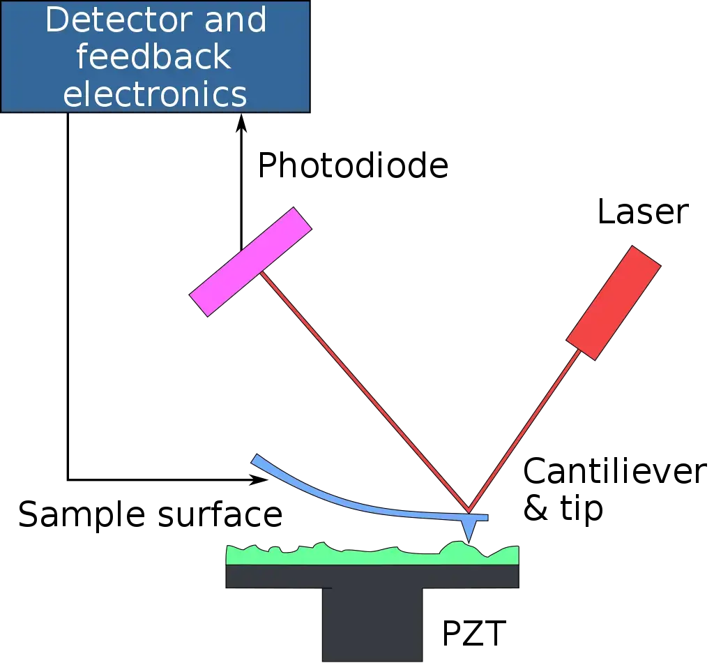
How does an atomic force microscope work?
Similar to an STM, a sharp tip is raster-scanned over a surface as a feedback loop fine-tunes the imaging parameters. Atomic force microscopes, in contrast to scanning tunnelling microscopes, do not require a conducting material. Atomic forces are used to create a map of the tip-sample interaction rather than the quantum mechanical impact of tunnelling.
Atomic force microscopy (AFM), also called scanning probe microscopy (SPM), can be used to measure practically any measurable force interaction, including van der Waals, electrical, magnetic, and thermal forces. Adjustments to the software and tweaks to the advice are necessary for some of the more specific methods.
Atomic force microscopy typically consists of four main parts: deflection, force measurement, angstrom-level positioning, and feedback loop control.
AFM Probe Deflection
Commonly found in AFMs is a laser beam deflection mechanism that works by having the laser beam bounce off the AFM’s reflecting lever and into a position-sensitive detector. Both the tip and the cantilever of an AFM are commonly microfabricated from Si or Si3N4. The typical tip radius ranges from a few nm to the tens of nm.
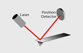
Measuring Forces
When imaging with an AFM, forces between the tip and sample can’t be ignored because they’re the basis of the technique. Instead of measuring the force directly, we can infer it from the lever’s deflection by knowing the cantilever’s stiffness.
By applying Hooke’s law, we obtain:
F = -kz
where F is the force, k is the lever’s stiffness, and z is the lever’s arc of bending.
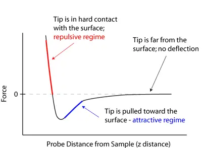
Feedback Loop for Atomic Force Microscopy
A feedback loop based on laser deflection regulates the atomic force microscope’s force and tip position. The AFM tip is attached to a cantilever, and a laser is reflected off the cantilever’s back. The laser’s position on the photodetector is fed back into the loop to monitor the surface and take readings as the tip moves across it.
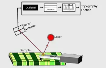
Parts of Atomic Force Microscope
The key components of an AFM include:
- Cantilever with sharp tip– A cantilever is a flexible beam with a sharp tip at the end. As the cantilever moves along the scan path, the sharp tip contacts the surface of the sample, bending the circuit that is scanned to determine surface properties.
- Laser and photodetector system– A laser is directed into the back of the cantilever. The laser beam reflects off the cantilever to a photodetector. The photodetector detects the change in the beam reflections resulting from the deflection of the cantilever and converts these changes into electrical pulses.
- Piezoelectric scanner– This component moves either the sample or the cantilever in the x, y, and z directions with incredible precision. This means that the scanning motion of the sample is so tiny that high-resolution images can be created.
- Detector and feedback circuit – The detector senses the deflection of the cantilever, and the feedback circuit compensates by moving either the cantilever or the sample to maintain a constant engagement force. This component ensures that the topography is rendered correctly.
- Control system and computer interface– The control system is the communication mode. It interprets the signal sent by the detector and ensures that the AFM is operating correctly. A scan type can be selected, information recorded, and images generated via the control system to render and interpret the desired imaged surface topography.
- Sample stage – The sample stage is the location of the sample, stable during scanning. It is usually capable of very fine adjustment to place the sample in the correct position under the AFM tip.
- Scan positioning system– The component that moves the AFM head to approach the sample before scanning. It consists of piezoelectric actuators for small translations and possibly another element for larger translations.
- Active Feedback System – The component that holds the AFM tip/sample in a constant pressure relationship to each other or moves the tip in the Z direction for topography scanning. Since the system compensates for height changes, it produces more accurate images.
- Control electronics and software– These dictate the scanning parameters and enable data collection and image processing by the AFM; they also provide the user interface for data processing and evaluation.
- Force measurement– AFM relies on forces to work, so forces also contribute to the final image. Forces are calculated relative to the amount of lever deflection since the lever spring constant is known. The lever spring constant is known via application of Hooke’s law, which says: F = -kz, where F = force, k = lever spring constant, and z = displacement of the bent lever.
Operating Procedure of Atomic Force Microscope
Step 1: Setup and Power Up
Use a surge protector to power on the AFM. Connect to the Nanoscope computer. Add the sample (glass slide) using adhesive tabs, super glue, or vacuum grease. Center the sample slide in the sample holder and use magnetic blocks to stabilize it.
Step 2: Add the Cantilever
Remove the cantilever from the top of the AFM and place it on the mounting bracket to add the cantilever. Place the tip of the AFM on the cantilever and return both to their places above the AFM.
Step 3: Adjust the Laser
Use the knobs on the right side to ensure that the beam hits the tip of the cantilever. The goal is for the strongest signal to detect a laser beam reflected by the photodetector.
Step 4: Start Scans
Make sure to calibrate your stage to your sample at the beginning of each new session via your program (if necessary). Be sure to check the z-height to avoid catastrophic failure while scanning.
Step 5: Measure
Choose the measurement mode based on your experiment: contact mode or tapping mode. In contact mode, maintain constant deflection by adjusting the tip-sample interaction forces. In tapping mode, vibrate the cantilever near its resonance frequency to reduce contact damage. Begin the scanning procedure by performing raster scanning across the sample surface, monitoring the feedback from the deflection of the cantilever.
Step 6: Collect and Process Data
Once the scan is complete, collect the data for analysis.. Deflection is a useful measurement because it provides a rendering of material properties beyond simple surface topography by mapping the displacement that the cantilever bending is subjected to due to the interaction forces between the tip and the sample.
Step 7: Post-measurement activities
Once the measurements are complete, carefully remove the probe from the material. Turn off the instrument in the reverse order of power-up and pay attention to all equipment.
Different modes of Atomic Force Microscope
AFM employs various modes to explore various nanoscale surface features. The principal AFM modes include:
- Contact Mode AFM- The AFM tip is pressed in constant contact with the surface of the sample. This is mainly for topographical imaging and evaluation of physical properties.
- Non-Contact Mode AFM – The AFM tip is held in a position slightly above the sample surface. This is for imaging softer samples so that no damage is inflicted.
- Tapping Mode AFM– With tapping mode, the AFM tip “taps” the sample surface at a fixed frequency and interacts with the sample. This is a contact/non-contact hybrid mode that provides great imaging quality and lower lateral forces on the sample.
- Magnetic Force Microscopy (MFM)– An MFM mode uses a magnetized AFM probe to respond to magnetic forces existing on the sample surface. This measurement is useful for mapping magnetic domains and properties of magnetic materials.
- Conductive Atomic Force Microscopy (C-AFM)- a conductive AFM tip scans the surface of a sample according to its electrostatic characteristics. This technique is frequently employed in semiconductor research, thin film applications, and basically any materials of interest that exhibit electrical conductivity.
Atomic Force Microscope Uses
- It measures surface topography at the nanoscale.
- Researchers use it to study molecular interactions.Scientists employ it to analyze mechanical properties.
- Engineers utilize it for semiconductor quality control.
- Biologists apply it to examine cell surface structures.
- Chemists use it to investigate material properties.
- Physicists employ it to study surface forces.
- Technicians use it for nanofabrication processes.
- Environmental scientists apply it to analyze pollutants.
- Medical researchers use it to study tissue samples.
Advantages of the Atomic Force Microscope
- It offers extremely high resolution. This allows you to see individual atoms and molecules, making it ideal for detailed surface analysis.
- It works in various environments. You can use it in air, vacuum, or liquid, which makes it flexible for different experiments.
- It is capable of imaging soft materials. Unlike electron microscopes, it does not require the sample to be in a vacuum, making it perfect for biological samples.
- You can measure forces with it. It can measure interactions between the tip and the sample, giving information about material properties like stiffness or elasticity.
- It provides three-dimensional images. By scanning the surface in different directions, it creates highly detailed 3D representations of samples.
- It is easy to use. With simple controls, even beginners can operate it with a short learning curve.
- It does not damage the sample. The scanning tip barely touches the surface, so it avoids causing any harm to fragile samples.
- It offers versatility. From imaging to measuring forces and mechanical properties, it can do many different types of analysis in a single tool.
- It gives high accuracy. The precision in its measurements is unmatched, making it essential for research and industrial applications.
- It is widely accessible. Many labs now have atomic force microscopes, which makes it easier to share resources and data within scientific communities.
Disadvantages of the Atomic Force Microscope
- Operating it requires specialized training and expertise.
- It is relatively expensive compared to other microscopes.
- The scanning speed is slower than some other microscopes.
- It has a limited scanning area, typically up to 150 micrometers.
- The image quality can be affected by thermal drift.
- It may produce image artifacts due to probe issues.
- Measuring steep walls or overhangs can be challenging.
- The probes can wear out over time, requiring replacement.
- It may not be suitable for all types of samples.
- The data analysis can be complex and time-consuming.
Atomic force microscope cost
Atomic force microscopes (AFMs) are relatively expensive scientific instruments, with prices ranging from tens of thousands to hundreds of thousands of dollars depending on the model and manufacturer. The cost of an AFM will depend on a variety of factors, including the type of AFM (e.g., contact mode, non-contact mode, tapping mode), the level of automation and features, the size and complexity of the system, and the manufacturer. AFMs can be purchased from scientific instrument companies, or they can be rented or leased from service companies. It is important to carefully consider your research needs and budget when selecting an AFM, and to compare prices from multiple sources before making a purchase.
How Atomic force microscope Works – Animation
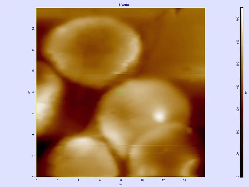
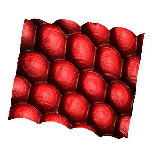
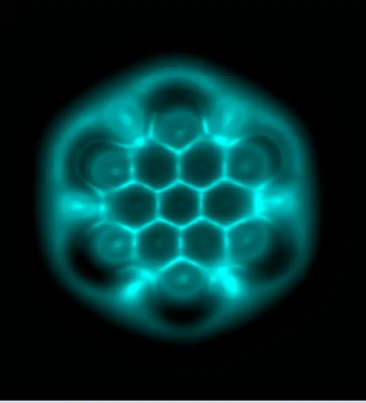
Atomic force microscope pictures/atomic force microscope images
- Binnig, G.; Quate, C. F.; Gerber, Ch. (1986). “Atomic Force Microscope”. Physical Review Letters. 56 (9): 930–933.
- Cappella, B; Dietler, G (1999). “Force-distance curves by atomic force microscopy”. Surface Science Reports. 34 (1–3): 1–104.
- Zhong, Q; Inniss, D; Kjoller, K; Elings, V (1993). “Fractured polymer/silica fiber surface studied by tapping mode atomic force microscopy”. Surface Science Letters. 290 (1): L688.
- Radmacher, M. (1997). “Measuring the elastic properties of biological samples with the AFM”. IEEE Eng Med Biol Mag. 16 (2): 47–57.
- Galvanetto, Nicola (2018). “Single-cell unroofing: probing topology and nanomechanics of native membranes”. Biochimica et Biophysica Acta (BBA) – Biomembranes. 1860 (12): 2532–2538.
- https://www.first-sensor.com/en/products/optical-sensors/detectors/position-sensitive-diodes-psd/
- https://www.researchgate.net/publication/256195163_The_Atomic_Force_Microscope
- https://www.sciencedirect.com/topics/nursing-and-health-professions/scanning-probe-microscope
- https://amedleyofpotpourri.blogspot.com/2018/09/atomic-force-microscopy.html
- http://nanoscience.gatech.edu/zlwang/research/afm.html
the way you structured it, just perfect.